
Surface roughness in the metal industry - What role does roughness play in the manufacturing process?
In purely scientific terms, roughness refers to the unevenness of the surface height and therefore ultimately how even, wavy or jagged a surface is. The roughness of a technical surface depends to a large extent on the upstream production processes and previous processing steps. The structure of the surface plays an important role not only in the area of adhesion or decoration, but also in the area of tribology, i.e. when surfaces move against each other.
In technical applications where subsequent process steps such as bonding or decorative coatings have to interact with the surface, its geometric structure, its topology, plays an important role. Even if it is not usually visible to the naked eye, surfaces appear as uneven as a mountain range under the microscope if they have not been processed extremely finely. As in the natural world, technical surfaces also tend to be smooth, regular and hilly with few peaks and edges or wildly jagged, mountainous surfaces. There are also any number of mixed forms. It should be noted that technical surfaces always have a surface topography.
Measurement of the roughness parameters Ra and Rz
In order to be able to reproducibly characterise the roughness of a surface from a technical point of view, precise definitions regarding the measurement method and its application are necessary. Mechanically measured roughness values, which are recorded with a so-called stylus instrument, are widely used and specified in many design drawings. During such a measuring process, a fine, high-precision scanning needle glides on the surface, similar to a pick-up on a classic record player, whereby the deflections in the Z direction are recorded metrologically. In the past, special precision dial gauges were used for this purpose, but nowadays the movements of the needle are analysed digitally. The average roughness depth Rz in particular is a relic of the time when such measurements had to be made without electronic support. The average roughness depth is therefore the mean value of the individual roughness depths of five consecutive individual measuring sections. Since DIN EN ISO 4287:1997, however, Rz is no longer an ISO characteristic value, but this does not change the fact that the value is still used.
The Ra value, on the other hand, is the more modern and more commonly used measured value today. Here, the peaks and troughs within a measuring section are recorded in order to obtain the average roughness of the metal surface, which is specified as a deviation from a virtually drawn centre line. Such measurements can be carried out either mechanically with a profilometer or with a laser scanner.
It is important to emphasise that these two measured values do not allow any statement to be made about the actual relief of a surface. Different surface structures can therefore lead to an identical Ra or Rz value with regard to the distribution of heights and depths. Surfaces with the same Ra or Rz values therefore do not necessarily look similar, nor do they necessarily have a comparable surface topology. In addition, both methods carry out line measurements, which means that the results only relate to a very thin line compared to the component expansion. These values are only meaningful beyond the direct measurement range if the surface is optically homogeneous and evenly processed and the preliminary processes are known. In order to determine the actual topology of a surface, spatially resolved measurements must be carried out. If there is any doubt about the homogeneity of the roughness, the measurements should be repeated in different areas. When interpreting stylus methods, the maximum roughness depth Rt or Rmax must always be interpreted. This is the maximum vertical difference between the deepest depth and the highest peak within the total measurement distance. In contrast to Ra and Rz, this value is an absolute, actually measured value. It can be assumed that the larger this value is and the more it deviates from the Ra or Rz values, the less uniform the surface will be.
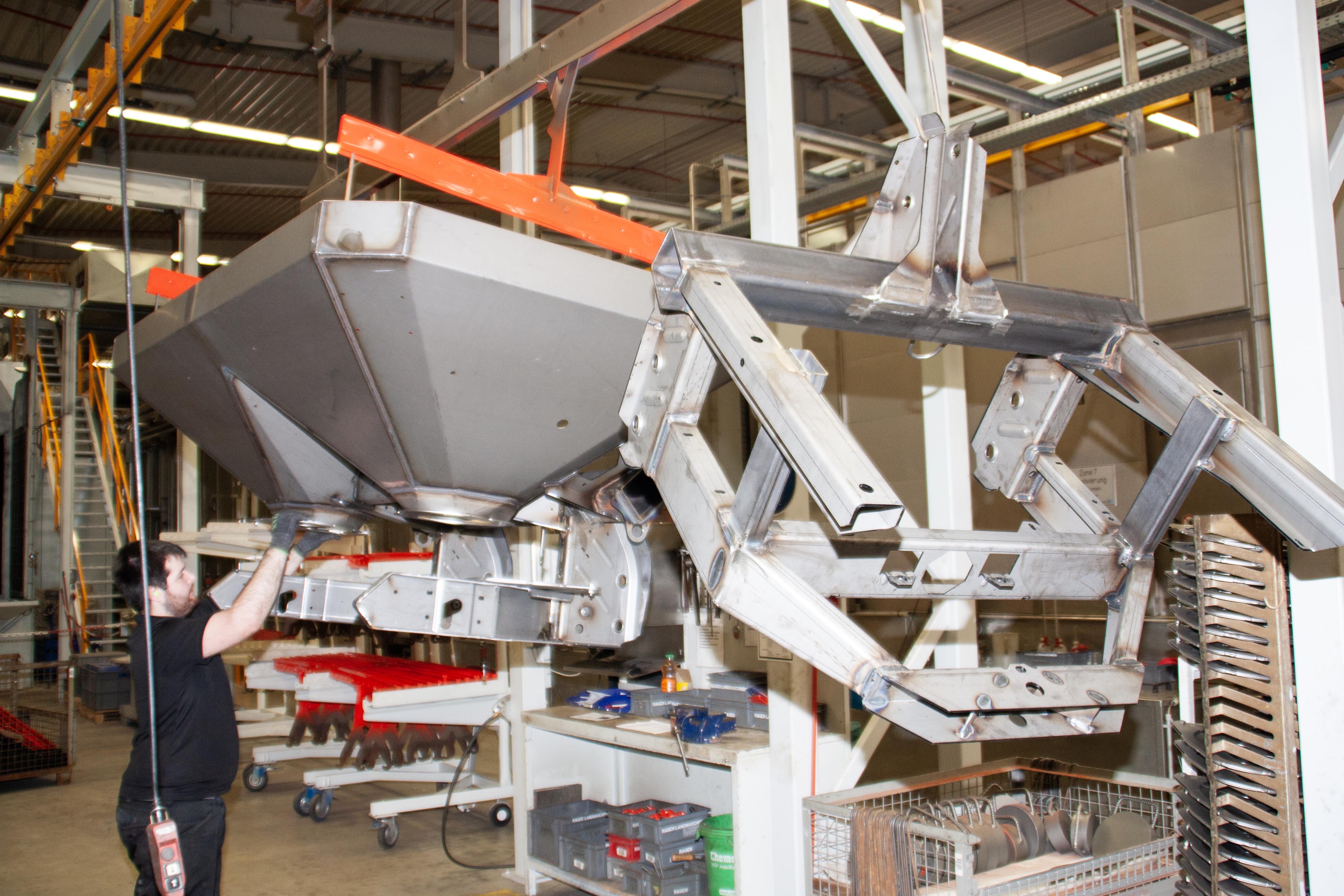
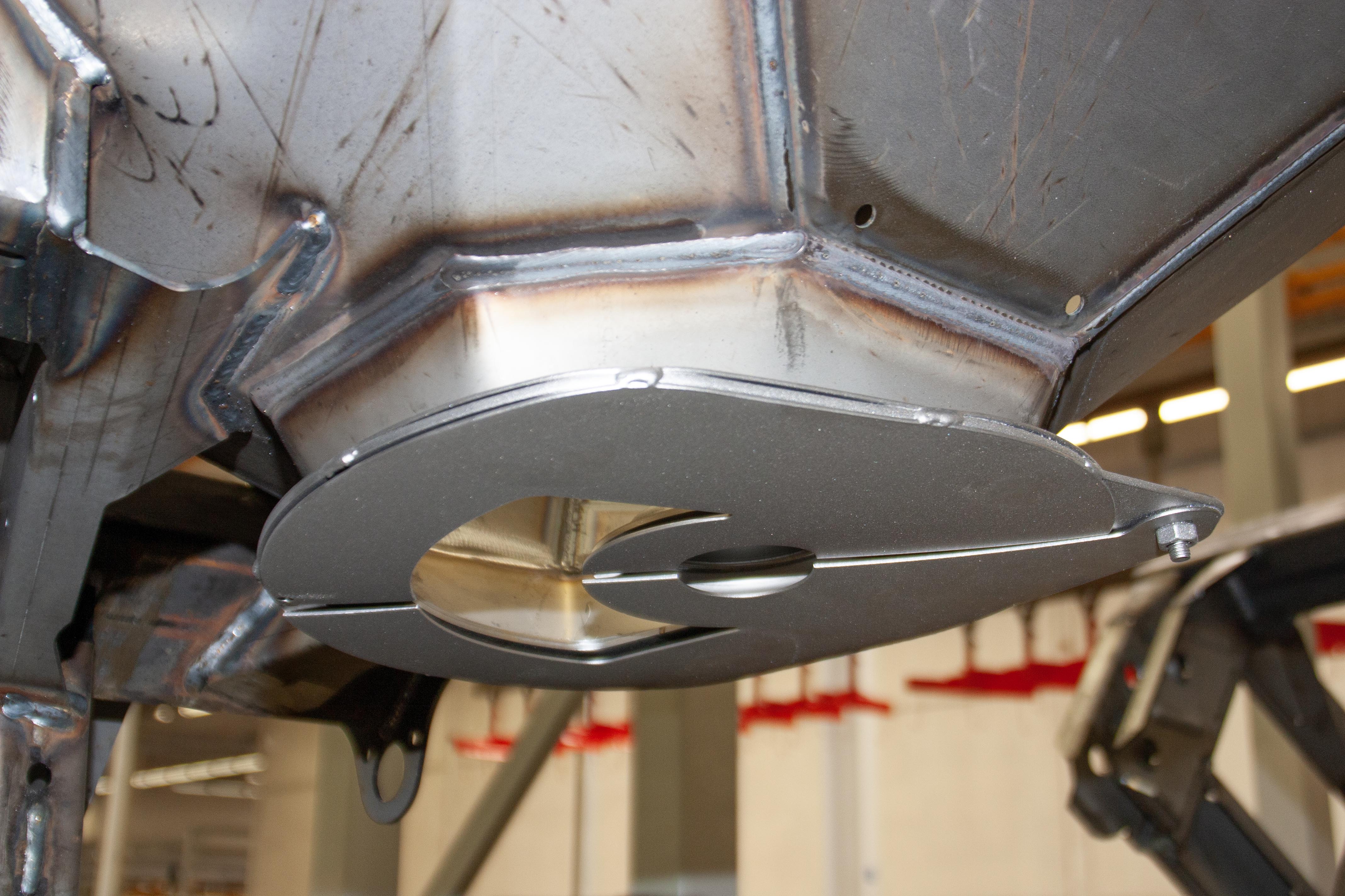
When designing a wheel blast machine, the arrangement and number of turbines can ensure that even complex geometries such as these assemblies are blasted reliably.
Image: CB
Visual evaluation of roughness
However, the technical properties of surfaces can also be assessed visually by the human eye. Even if a certain degree of subjectivity must be taken into account here and the observer's level of training plays a major role, the properties of the surface as a whole can be recorded, which is a considerable advantage over the measurement methods described above. Such a visual test is generally quicker to perform than reliably determining the roughness with a stylus instrument. Especially in the hands of an experienced and careful employee, such a visual assessment can allow a very accurate statement to be made. A well-known method for this is the so-called rugotest. Similar to colour charts used to evaluate colour nuances, substrates with comparison surfaces with defined properties are used here. For example, milled or otherwise mechanically processed sample pieces with different roughnesses can be used for comparison.
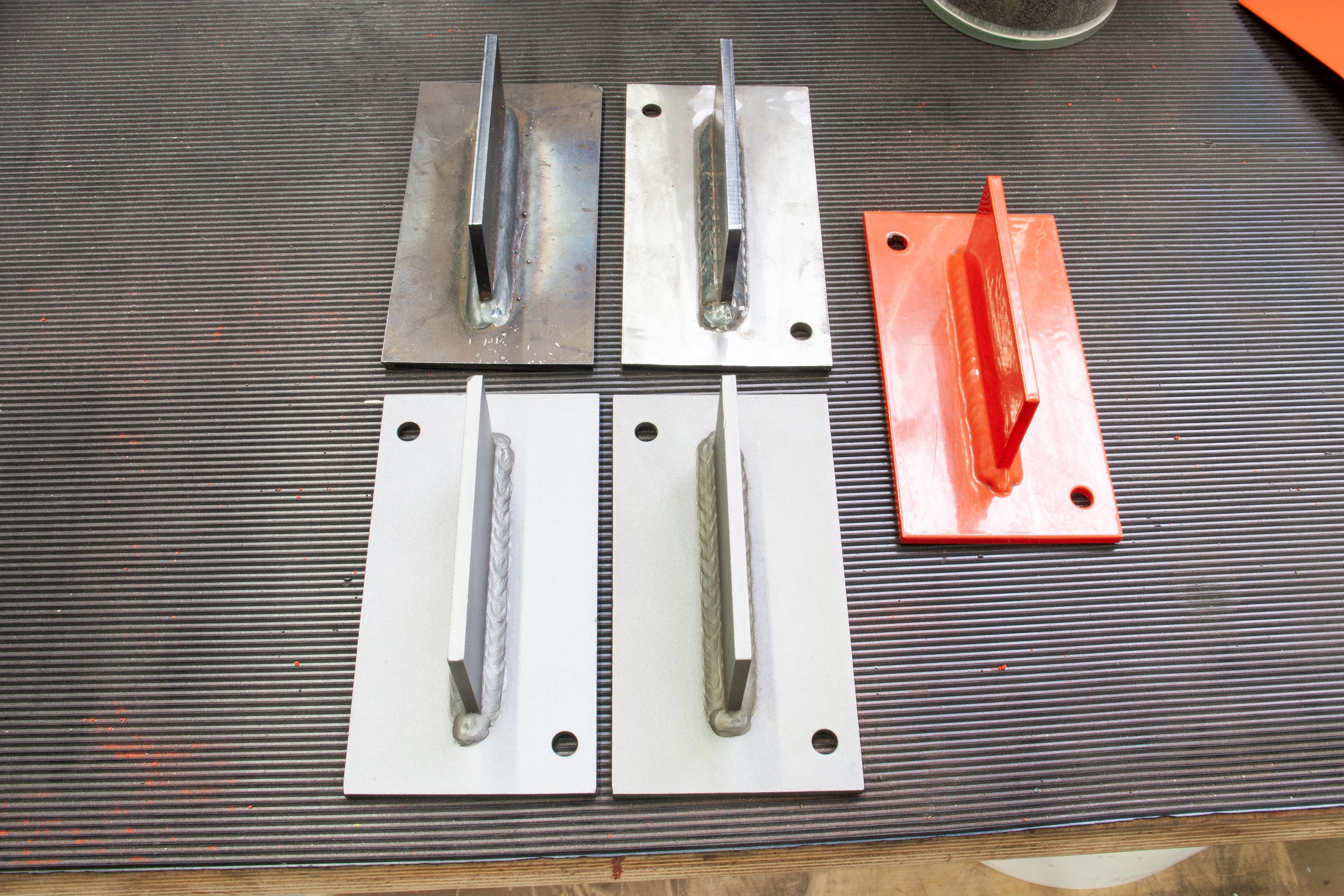
At the top left is an untreated sample workpiece, on the right it was not blasted evenly or for long enough. The parts on the bottom left and right are blasted evenly with different parameters. On the right is a component blasted and painted in accordance with SA3.
Image: CB
Digital characterisation of roughness and surface profile with microscopes
Modern optical measurement methods with microscopes and digital evaluation of the surface topography now complement the possibilities for characterising surfaces. The advantages of such holistic measurement methods over stylus methods lie in particular in the fact that values such as Ra or Rz are only of limited significance when it comes to the visual or adhesive properties of a surface, as they do not allow a geometric assessment of the surface topology on the basis of the measurement principle, as already mentioned.
What do the roughness values say about the surface quality?
In principle, the roughness values of a surface can be used to draw conclusions about its origin, as every process for producing a semi-finished product, geometry or surface leaves behind characteristic roughness values and structures. The roughness classes according to DIN EN ISO 1302 provide a good overview of what is possible with different machining processes - even though they have now been officially replaced by the ISO series of standards ISO 21920-1 to 3. However, due to its many years of use, DIN EN ISO 1302 is still very much present in practice. Nevertheless, it is advisable to familiarise yourself with the new ISO 21920, particularly because the functional characterisation of surfaces has been significantly further developed.

It is important to remove blasting agent residues from blasted components; there is a return device for the blasting agent under the grid in the floor. Good and even lighting helps to assess the blasting result.
Image: CB
Roughness classes and processing methods
With an N value of 10 and an Ra value of 12.5, chill casting produces an extremely rough surface. Roughing, a machining process with high feed and cutting speeds, is many times smoother and more even. Such surfaces fulfil roughness class N8 and have Ra values of around 3.2. Roughness classes N8 and N7 are generally considered to be coarse surfaces; surfaces below this are considered unmachined. A surface is only considered fine once it has been sanded. In the first stage, coarse sanding, RA values of 0.8 are achieved. From pre-grinding to fine grinding, the surface becomes increasingly smoother; in fine grinding, the Ra values are 0.2 and the roughness class is N4. Surfaces are considered polished from roughness classes N3 to N1. It is worth noting that even with ultra-fine grinding and Ra values of 0.1 µm, machining marks are still visible. These only disappear from an Ra value of 0.025. Ultra-precision diamond turning with an Ra value of 0.0002 marks the end point of exciting machining.
The respective Rt values are also always defined in the respective roughness classes, so RT values of up to 25 µm are permissible for an N8 roughness class and only 0.1 µm for an N3 roughness class.
| N | Ra / µm | Max roughness depth Rt μm | Remark |
|---|---|---|---|
| 0,0002 | 0,2 | Ultra-precision diamond turning | |
| 1 | 0,025 | 0,4 | no visible traces of processing |
| 2 | 0,5 | 0,8 | - |
| 3 | 0,1 | 1,6 | ultra-fine grinding |
| 4 | 0,2 | 3,2 | Fine grinding |
| 5 | 0,4 | 6,4 | Pre-grinding |
| 6 | 0,8 | 16 | Rough grinding |
| 7 | 1,6 | 25 | arbitrate |
| 8 | 3,2 | 40 | Roughing |
| 9 | 6,3 | 63 | - |
| 10 | 12,5 | 100 | Mould casting |
| 11 | 25 | - | |
| 12 | 50 | - |
Table 1: Here the roughness classes are compared with the machining methods.
Surface roughness in manufacturing technology
For reasons of economy and productivity, a designer should always enter the lowest possible surface quality for his application in his drawing. This is because each additional machining step, including polishing, significantly increases production costs. A distinction is made in particular between tribiological requirements, for example for sliding pairings. If a shaft slides in a bearing, the roughness as well as the surface profile must be designed in such a way that a continuous lubricating film can be formed and excessive heating due to friction is prevented. Another functional requirement relates to the opposite, when a certain surface roughness is desired in order to improve the adhesive strength of bonds or coatings.
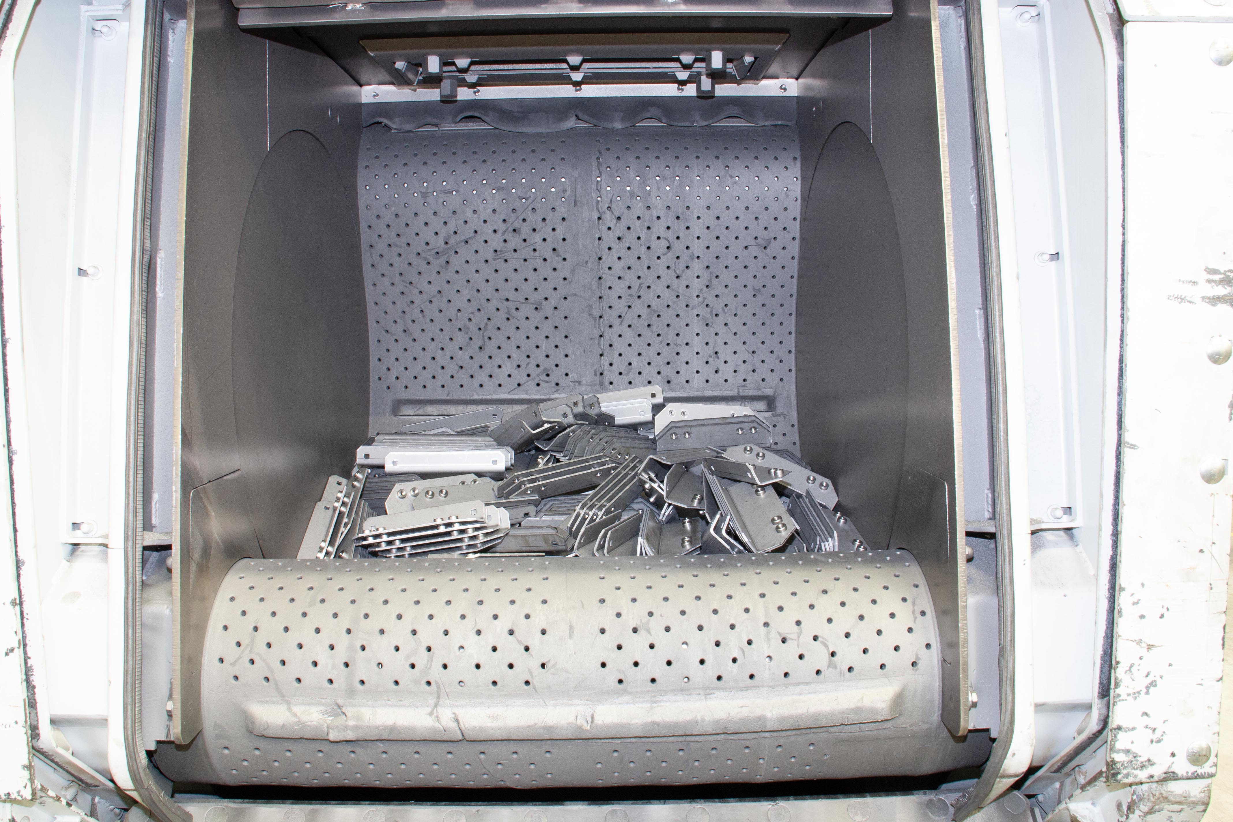
Troughed belt blasting systems are suitable for small parts, where the components are circulated by a type of conveyor belt and thus exposed to the blasting agent. After a certain time, all components are blasted evenly. The components must not be too large or heavy for this.
Image: CB
The three adhesion mechanisms
In the case of a decorative coating, for example a paint finish, the surface must be homogeneous and smooth enough so that the substrate structure cannot be seen through the coating. At the same time, however, it should have a certain roughness, as this in turn improves the adhesion of the coating. This adhesive strength is based on three mechanisms, firstly on the chemical and physical bonding forces that act between the molecules and atoms. In addition, there is the mechanical interlocking that occurs when the cured coating interlocks with the substrate.
Furthermore, the roughness and also the geometry of the unevenness have an influence on the surface energy and thus, in addition to the cleanliness and the basic physical-chemical properties of a substrate, have an influence on whether a surface is well wettable. This in turn is an important prerequisite for any type of coating or bonding.

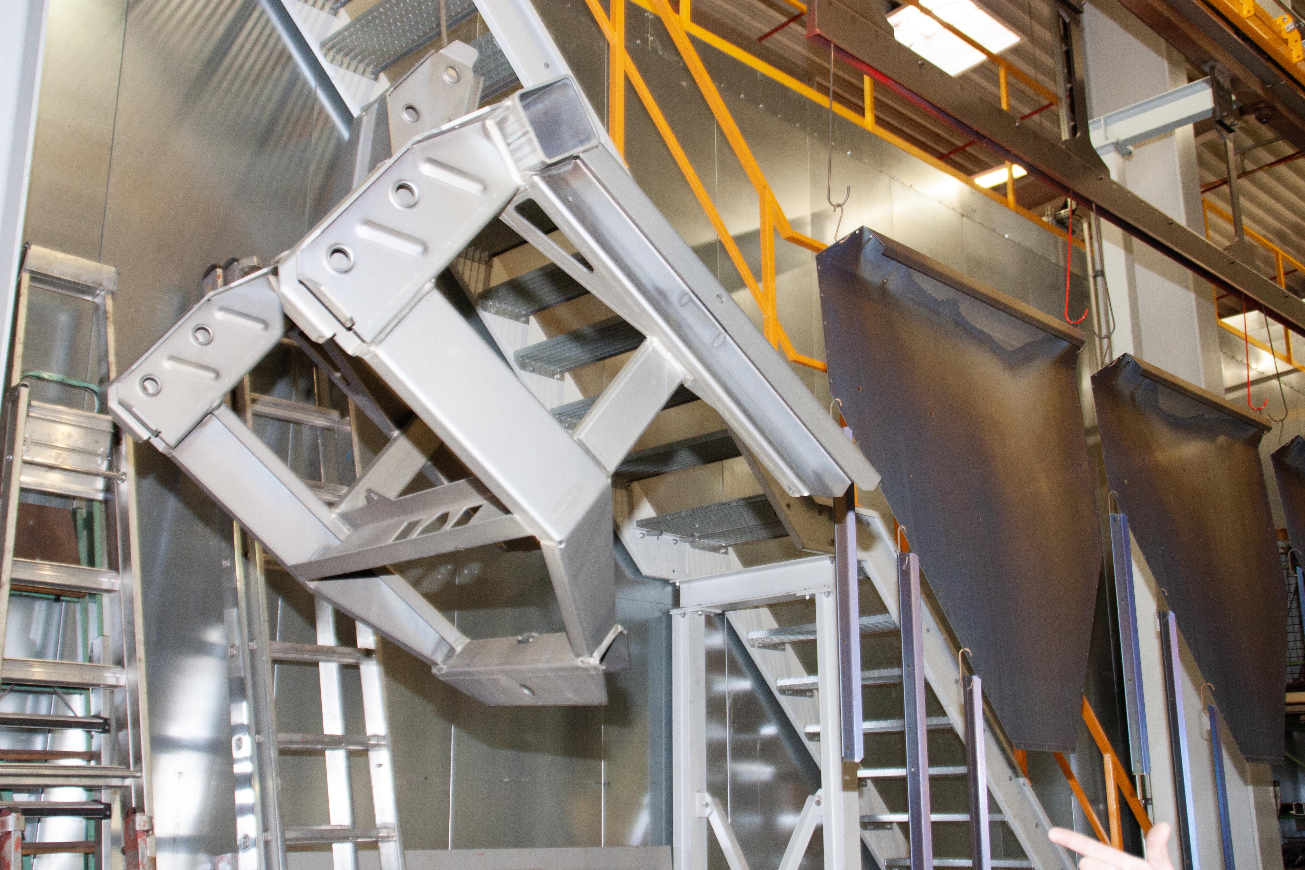
Only if the surface has been evenly and thoroughly pre-treated are uniform and, above all, durable coatings possible for such welded components with complex geometries. The smoothing and removal of burrs and edge rounding play an important role here.
Image: CB
Visual requirements
Of course, there are also visual requirements for the roughness and homogeneity of surfaces. As a rule, visible surfaces of machines or components must have a qualitative appearance defined and desired by the manufacturer. To achieve this, the surface beneath the decorative coating plays a decisive role. The smoother and glossier the coating is, the more important it is to have a homogeneous, smooth surface, as even small irregularities can affect the paint surface. How much a paint can conceal in this respect varies greatly; textured paints can conceal coarser surfaces, while high-gloss paints are very sensitive. There are basically two ways to create a visually high-quality surface. A surface that has only been lightly treated can be smoothed with several layer systems, for example with a leveling primer or filler and filler systems as well as high paint layer thicknesses with a specially designed formulation. Or the surface is treated mechanically. In practice, a combination of mechanical pre-treatment and correspondingly coordinated coating systems are generally used. In principle, blasting offers a very economical and effective way of pretreating surfaces evenly and cost-optimized. In this context, EN ISO 12944-4 defines four relevant degrees of preparation for the “shot blasting” process.
| Degree of preparation | Key features of the surface |
|---|---|
| Sa 1 | Loose impurities are removed |
| Sa 2 | Almost all impurities are removed |
| Sa 2,5 | Only shadowy contamination still recognisable |
| Sa 3 | Uniform regular metallic surface |
Table 2: The degree of preparation is important for subsequent further processing and which surface quality can be achieved.
The table shows that at least SA class 2.5 must be achieved for subsequent painting, and even SA 3 for higher appearance requirements. Another advantage of blasting processes is that edges are always deburred, thus reducing the so-called edge alignment that is problematic with paints. Basically, the sharper an edge, the thinner the paint layer that forms directly over this edge after drying and the more susceptible this area is to corrosion damage later on.
Manual or automated blasting
If a blasting process is required to produce the desired surface quality, it is necessary to decide whether a manual or automated blasting process is suitable. Manual blasting processes have the advantage of relatively low investment costs, and the size and geometry of the components to be blasted are flexible within very wide limits. However, working in full protection in the blast cabinet is both strenuous and time-consuming. In addition, the result of the blasting process in terms of homogeneity and sufficient surface finish is highly dependent on the working method and experience of the blaster. Manual blasting processes often work with the compressed air blasting method, which requires considerable capacities in the area of compressed air generation. Compressed air is also a very expensive energy source - all the more so in times of high energy prices.
An alternative to compressed air blasting is wheel blasting. In this process, blasting material is accelerated by a rotating paddle wheel and propelled towards the object to be blasted. As a rule, several such blast turbines are arranged in a system in such a way that all areas of a component to be blasted can be covered. As soon as the component or components are in the system, the blasting process is fully automated and is highly reproducible if the system is operated correctly. However, only components for which such a wheel blast machine has been designed and optimised in terms of size and geometry can be processed.
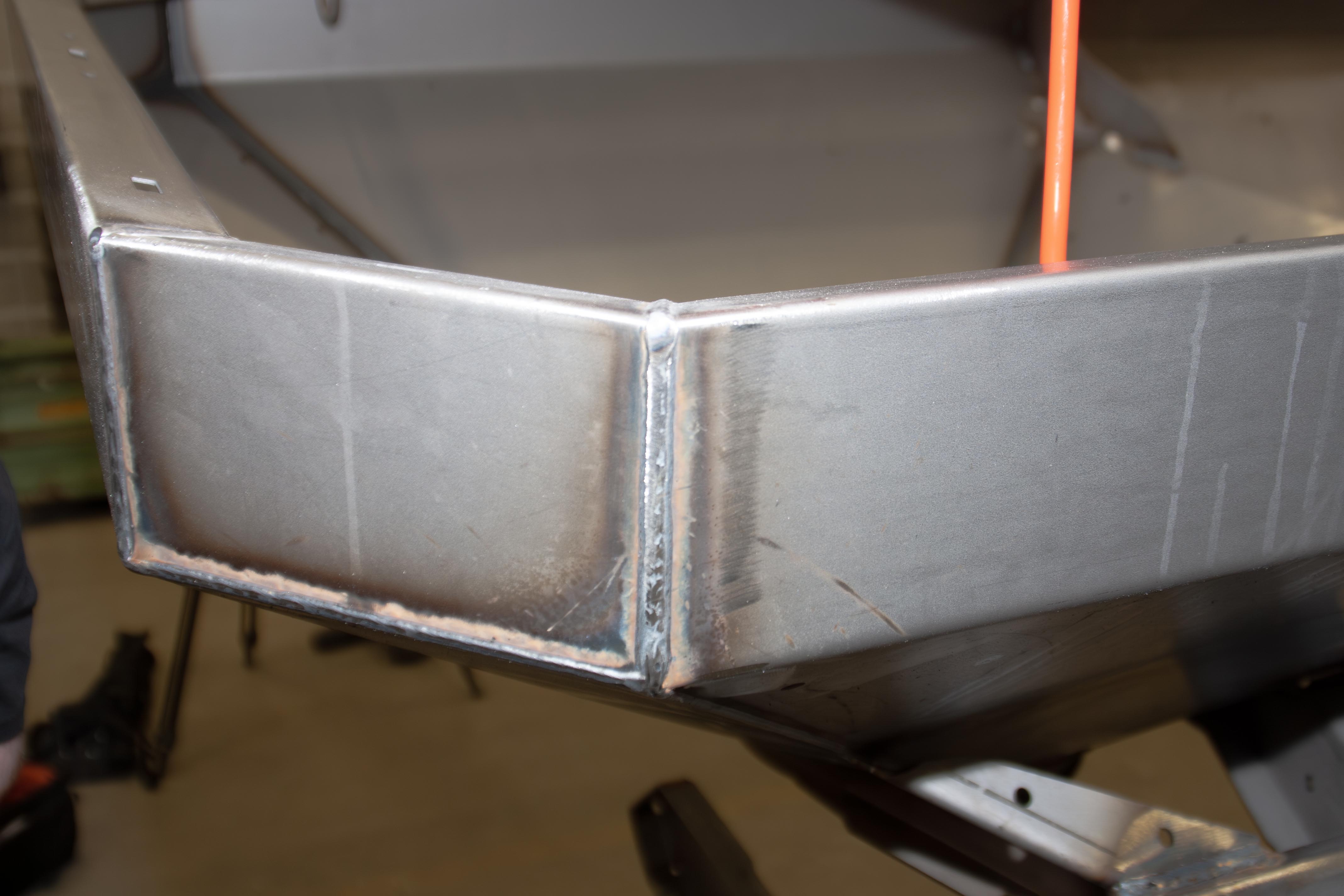
Automated blasting processes are very suitable for smoothing weld seams and evenly removing welding beads and traces of the welding process.
Image: CB
High parameter diversity for blasting
The principle of a blasting process sounds very simple at first: particles are accelerated onto a surface. The properties of these particles, such as weight, strength, size and geometry, as well as their speed, i.e. their kinetic energy, can be used to control the result over a very wide range. Basically, the mass of the abrasive, i.e. the particle size, but also the ejection speed, must be adjusted to the substrate and, above all, its material thickness, otherwise the force exerted by the abrasive can lead to deformation.
The shape of the abrasive also has a major influence on the roughness of the surface, for example whether it is angular or round. If, for example, zinc surfaces are to be prepared for subsequent coating, angular blasting media is often used for sweeping in order to create as many points of attack as possible for the paint layer to bond with the substrate. Mineral abrasives are used quite frequently in manual blasting processes; they are relatively inexpensive to purchase, but lead to a high dust load and high system wear, while at the same time the abrasive very quickly turns into dust. Especially in automated blasting processes, so-called wheel blasting systems, steel or stainless steel abrasives are often used. However, blasting can also be very gentle; there are soft blasting media such as walnut shells, which remove superficial or stubborn soiling but leave the substrate untouched. There are many ways to achieve very smooth and decorative surfaces using blasting processes. For example, glass beads or soft materials such as aluminium can be used to matt or polish. In this respect, blasting processes are extremely versatile.
Multi-axis abutting weld seams, a fundamentally complex geometry and undercuts are no problem for automated blasting processes. It would be a major challenge for a manual coating process to blast every square centimetre evenly.
Image: CB
Brief summary and conclusion
Roughening metal sounds like a trivial process at first, but this does not apply to industrial processes where reproducibility and reliability of results are crucial for the achievable quality. The measurement of roughness values using stylus methods, in which the surface properties are represented in simplified form as calculated mean values, is widespread. This simplification means that surfaces with identical Ra or Rz values do not necessarily have a similar surface profile and therefore the same properties. If the actual surface profile plays an important role for an application, spatially resolved analyses must be carried out, for example using modern microscope systems. This can be particularly important in the context of bonding and tribological applications where the actual surface profile plays an important role. When it comes to achieving a high level of corrosion protection, the absolute roughness of a surface is not so important, but the deburring of edges is a very decisive factor. For many of the applications mentioned here, blasting processes are well suited to producing homogeneous and reproducible surfaces. Automated wheel blasting systems can produce a high and reproducible surface quality economically, especially for series components.
Here you can see components in a blasted state - they are evenly blasted down to the furthest corners and have a matt shine. An ideal basis for painting.
Image: CB